
Notice
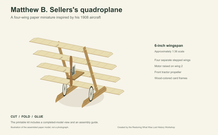
Sketch the airplane from the side. How do the wings overlap, and which wing carries the motor?
Explore four staggered wings, a raised engine, and the care it takes to turn a flat drawing into a three-dimensional model.
Created by the Restoring What Was Lost History Workshop
Free educational use. Times are estimates; allow extra time for drying, practice, and younger builders.
Use these stages to plan your work alongside the instructions inside the model PDF.
Find the completed-model picture and wing-order drawing inside the PDF. Identify the front, the four wings, the two frames, and the small motor parts before cutting.
Fold and glue the four wings, matching frame pairs, and propeller faces as shown. Let them dry flat, then cut the outlines, wing slots, and frame notches. Keep small parts together.
Dry-fit the rear crossbar between the parallel skids. Starting with the lowest wing, slide each wing from back to front until its slots meet the frame notches. Use the PDF’s wing-order drawing.
Let the wings set the frame spacing, about two inches apart. Check that the frames are upright before gluing the eight wing joints and the crossbar tabs.
Glue the platform’s pale patch onto WING 2 with its long end facing forward. Follow the PDF for the motor’s two tabs and propeller hub. This is a display model; it is not designed to fly.
Sketch the airplane from the side. How do the wings overlap, and which wing carries the motor?
At 1:36 scale, one model inch represents three feet. What full-size wingspan does a six-inch model represent? Show your calculation.
Compare the model with a historical description. Name one feature the model represents and one detail that the paper construction simplifies.
Spend 5 minutes noticing the model, 10 minutes exploring the historical context, 20 minutes on a first building stage or measurement activity, and 10 minutes sharing observations. Plan additional sessions for finishing longer builds. The teacher handout includes a lesson plan and learner pages.
Sellers experimented with different aircraft arrangements. This simplified display model follows the front-propeller arrangement described in Flight on October 14, 1911, with the motor and tractor propeller on the second wing from the bottom. It does not establish the configuration of every Sellers aircraft or reproduce his first airplane exactly.
Explore the Sellers exhibitCreated by the Restoring What Was Lost History Workshop. You’re welcome to print copies for classrooms, family activities, and community displays.